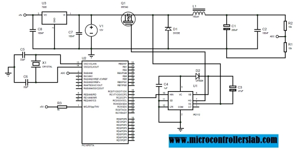
Buck Converter Mosfet Driver
Typically, buck converters have a bootstrap gate driver 1 and an N-channel MOSFET, or a P-channel MOSFET. 1 Bootstrap gate driver (see also here) is not the only option for N-challel MOSFETS. Other options: gate driver transformer, additional supply rail for gate driving with elevated voltage.
Analysis of Buck Converter Efficiency Abstract The synchronous buck circuit is wildly used to provide non-isolated power for low voltage and high current supply to system chip. To realize the power loss of synchronous buck converter and to improve efficiency is important for power designer.
The application note introduces the analysis of buck converter efficiency and realizes major power component loss in synchronous buck converter. Buck converter power loss analysis To realize the power loss in converters is important for converter design optimization. Figure1 shows the general single phase synchronous buck converter circuit. The major power losses in synchronous buck converter circuit are listed as bellow: A: Power semiconductor loss B: Inductor loss C: Driver loss D: PCB trace loss Figure 1. Synchronous buck converter Power loss calculation Low-power loss and highly efficient synchronous buck converters are in great demand for advanced micro-processors.
The application note introduces and provides how to calculate the majority of power losses in a typical synchronous buck converter occur in the following components based on that the converter works in continuous conduction mode (CCM) fixed switching frequency, fixed input voltage and fixed output voltage. A: Power semiconductor loss: HMOS (High-Side MOSFET) summarizes to include: switching on & off and conduction loss. LMOS (Low-Side MOSFET) summarizes to include: conduction, dead-time and reverse recovery charge loss. HMOS switching on loss: Figure 2. HMOS Driver switching on Figure 3. HMOS switching on loss area HMOS conduction loss: The conduction loss of high-side MOSFET is determined by the on-resistances of the MOSFET and the transistor RMS current. HMOS conduction on Figure 5.
Buck Converter Mosfet Waveform In Cro
HMOS conduction on period LMOS conduction loss: Figure 6. LMOS conduction on Figure 7. LMOS conduction on period LMOS dead time body diode loss: Dead-time loss is induced by LMOS body diode conduction during dead-times. LMOS body diode conduction on: Figure 9. LMOS body diode conduction on period LMOS reverse recovery charge loss: Figure 10.
Buck Converter Mosfet Driver Download
LMOS body diode reverse recovery period B: Inductor DC & AC loss Inductor DC loss: Figure 11. Current through inductor path Figure 12.
Inductor current path period Inductor core loss: Inductor core losses are major caused by an alternating magnetic field in the core material. The losses are a function of the operating frequency and the total magnetic flux swing. The core loss may vary from one magnetic material to another. Inductor ripple current Figure 14. Core loss curve The calculated and/or measured core loss is often directly provided by the inductor supplier. If not, a formula can be used to calculate the core loss as bellow: The PL is the power loss (mW), Fsw: operating frequency B: peak flux desity in Gauss V e: effective core volume The specific value of C, X and Y are core loss parameters for each material C: Gate driver loss.
How to turn on a buck transistor via a bootstrap circuit? Vray 2.0 for 3ds max 2009. In my circuit, I use a AVR microcontroller to turn on and off a buck switch. What circuit should I use here? Previously, I used optocoupler which does not have a fast response. I like to turn on and off the transistor for no more than 500 ns on/off transition.
There are some high side low side ICs which are designed for bridges and I am not sure if they would work for here. Solutions with BJT/Capacitor/Diodes are very pleasant to me though I dont limit myself to only those solutions. You're using an N-channel MOSFET, for it to come into an 'on' (low-resistance) state Vgs must be large, let's say 5V. The highest voltage you have is 36 V (+ node of battery). Even this will not fully turn-on the NMOS. You would need at least 41 V on the gate.
Instead I would use a PMOS, then you can just pull the gate low. But to switch it OFF the gate of the PMOS must be pulled to 36 V! An AVR cannot handle this so you would need an additional transistor to pull the gate of the PMOS down.
Tutorial adobe premiere cs3 bahasa indonesia. Adobe Premiere merupakan sebuah yang cukup populer dikalangan editor - editor profesional, kehandalan dari software ini sudah tidak perlu diragukan lagi. Akan tetapi bagi sobat yang sudah banyak berkecimpung dengan dunia multimedia, pastinya sudah mengenal penggunaan software Adobe Premiere ini. Fitur - fitur yang ditawarkan sangat membantu kita untuk memanipulasi sebuah video sehingga menghasilkan hasil editing yang cukup memuaskan.
A 1n4001 is not fast enough for these type of applications, better use a Schottky diode. There is a fundamental flaw in your circuit! It has no current limiting! This is an issue, especially when the battery pack has a low voltage and the inductor saturates. The current would only be limited by the series resistance of the batteries and this is BAD, avoid at all cost!

(Your wires could melt!) Have a look at document form TI and learn how it's done! If you want to actually build this then I strongly advise you to use an IC for that but pay attention to the 36V battery voltage, not all ICs can handle that. Also there are a lot of ready-built modules for sale on eBay, that would be more convenient as the layout of a switched converter is not something for a beginner. In general, you don't want an AVR or any micro Controller to control a DC-DC converter switch. They're too slow, software could get stuck with the switch turned on.